


When replacing a three-wire DC sensor — whether it is an inductive proximity switch, a photoelectric sensor, an ultrasonic sensor, or a capacitive sensor — one of the most important things to determine is the output type: PNP or NPN. Installing a sensor with the wrong output type into an existing circuit can prevent the system from functioning and, in some cases, can damage the sensor or the connected input device.
Ideally, this information is printed directly on the sensor body or recorded in the equipment's maintenance documentation. In the real world, labels wear off over years of service, documentation goes missing, and sensors get replaced with whatever was available at the time without updating the records. When that happens, a simple test with a digital multimeter will give you a definitive answer.
Understanding PNP vs. NPN Output
Before performing the test, it helps to understand what PNP and NPN mean in practical terms.
A PNP sensor (also called a "sourcing" sensor) provides a positive voltage on its output wire when it is activated. When the sensor detects its target, it connects the output wire to the positive supply voltage. The output "sources" current to the connected load.
An NPN sensor (also called a "sinking" sensor) connects its output wire to the negative terminal (ground) when activated. When the sensor detects its target, the output wire is pulled to ground, "sinking" current from the load.
Both types are equally common in industrial automation. PLC input cards are designed to accept either type, but a given input card is typically designed for one or the other — sinking inputs work with PNP sensors, and sourcing inputs work with NPN sensors. Matching sensor output type to PLC input type is essential for correct operation.
Wire Color Convention
Most three-wire DC sensors follow the standard IEC wire color convention:
- Brown — positive supply voltage (typically 10-30 VDC)
- Blue — negative supply voltage (0V / common)
- Black — signal output wire
This convention is not universal — some sensors use different color coding, particularly older equipment or products from certain manufacturers. Always confirm wire function against the sensor's data sheet when available.
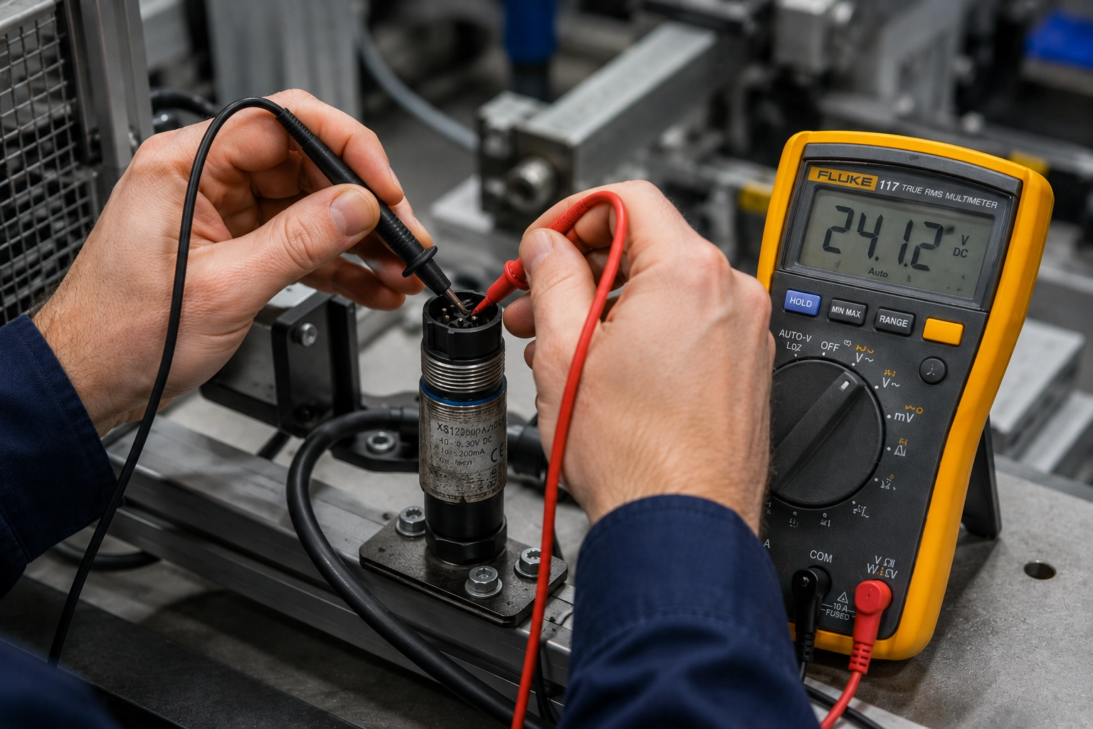
Equipment Required
- Digital multimeter capable of reading DC voltage
- An appropriate DC power supply for the sensor (check the sensor's voltage rating — typically 10-30 VDC)
- The sensor to be tested, with wiring accessible
Safety Note
This test is performed with the power supply energized. Use caution when working with live circuits. Ensure all connections are secure before applying power and avoid touching bare conductors during testing.
Step-by-Step Test Procedure
Step 1: Configure the Multimeter
Set the multimeter to measure DC voltage. On the meter's selector dial, look for "VDC," "DCV," or a symbol showing three dashed lines over a solid line (the standard symbol for DC voltage). Select the 600V range or the next range above the supply voltage being used — for a 24 VDC sensor supply, the 200V DC range is appropriate.
Step 2: Power the Sensor
Connect the sensor's brown wire to the positive terminal of the power supply and the blue wire to the negative terminal. Apply power. Many sensors have a status LED that indicates when the sensor is powered on — confirm the sensor is receiving power before proceeding.
Step 3: Connect the Multimeter for the First Test
Touch the black (negative) probe of the multimeter to the blue wire of the sensor (the 0V / negative supply wire). Touch the red (positive) probe of the multimeter to the black wire of the sensor (the signal output wire). With the sensor in its non-detecting state (no target present), the meter should read approximately 0 volts.
Step 4: Activate the Sensor
Force the sensor to detect its target:
- Inductive proximity sensor — hold a small piece of ferrous metal in front of the sensor face within the specified sensing range
- Photoelectric sensor — block the infrared beam between transmitter and receiver, or for a diffuse-mode sensor, hold an object in front of the sensing face
- Capacitive sensor — hold your hand near the sensing face
- Ultrasonic sensor — hold your hand or a flat object at an appropriate distance from the face
Confirm that the sensor's status LED indicates detection of the target.
Step 5: Read the Meter
With the target present and the sensor activated, observe the meter reading:
- If the display reads between 10 and 30 volts (approximately equal to the supply voltage), the sensor output is PNP (sourcing). When activated, the sensor is connecting the output wire to the positive supply voltage, which is what the meter is detecting.
- If the display remains at or near 0 volts, the sensor output is likely NPN (sinking). Proceed to the confirmation test below.
Confirming an NPN Output
If the initial test shows the meter reading staying near 0V when the sensor is activated, perform this secondary test to confirm an NPN output:
- Move the red (positive) probe of the multimeter to the brown wire (positive supply voltage).
- Move the black (negative) probe to the black wire (signal output wire).
- With the sensor not detecting a target, the meter should read between 10 and 30 volts — close to the supply voltage.
- Now activate the sensor by presenting the target.
- When the sensor detects the target, the meter reading should drop to near 0 volts.
This behavior — high voltage when not detecting, low voltage when detecting — confirms the output is NPN (sinking). The sensor, when activated, is connecting the output to the 0V rail, which is seen on the meter as a drop to zero.
Interpreting Results
| Test Condition | Meter Reading | Output Type | |---|---|---| | Sensor activated, probe on output vs. 0V | 10-30V | PNP (Sourcing) | | Sensor activated, probe on output vs. 0V | ~0V | NPN (Sinking) | | Sensor not activated, probe on supply+ vs. output | 10-30V, drops to 0V when activated | NPN confirmed |
What to Do with This Information
Once the output type is confirmed, you can properly match the sensor to the PLC input card, relay, or other receiving device in the circuit. If the existing input card requires PNP and the sensor is NPN (or vice versa), you have several options:
- Replace the sensor with the correct output type — the most straightforward solution when a compatible replacement is readily available
- Use a signal converter — small DIN-rail mounted devices that convert NPN to PNP or vice versa are available and can resolve a mismatch without requiring sensor replacement
- Reconfigure the PLC input card — some input cards are configurable for either sinking or sourcing operation; consult the PLC documentation
Taking the time to properly identify sensor output type before installation eliminates a common source of commissioning errors and ensures the control system responds correctly to sensor signals from the first power-up.