


Many industrial and agricultural processes involve storing bulk materials — wood chips, grain, plastic pellets, powders, sand, gravel, or liquids — in large bins, hoppers, silos, or tanks. Knowing the level of material in these containers is essential for process control, inventory management, and preventing costly overflows or unexpected runouts. When there is no obvious window or sight glass to observe the level directly, an industrial ultrasonic sensor with an analog output provides a reliable and non-contact solution.
Why Ultrasonic Sensing?
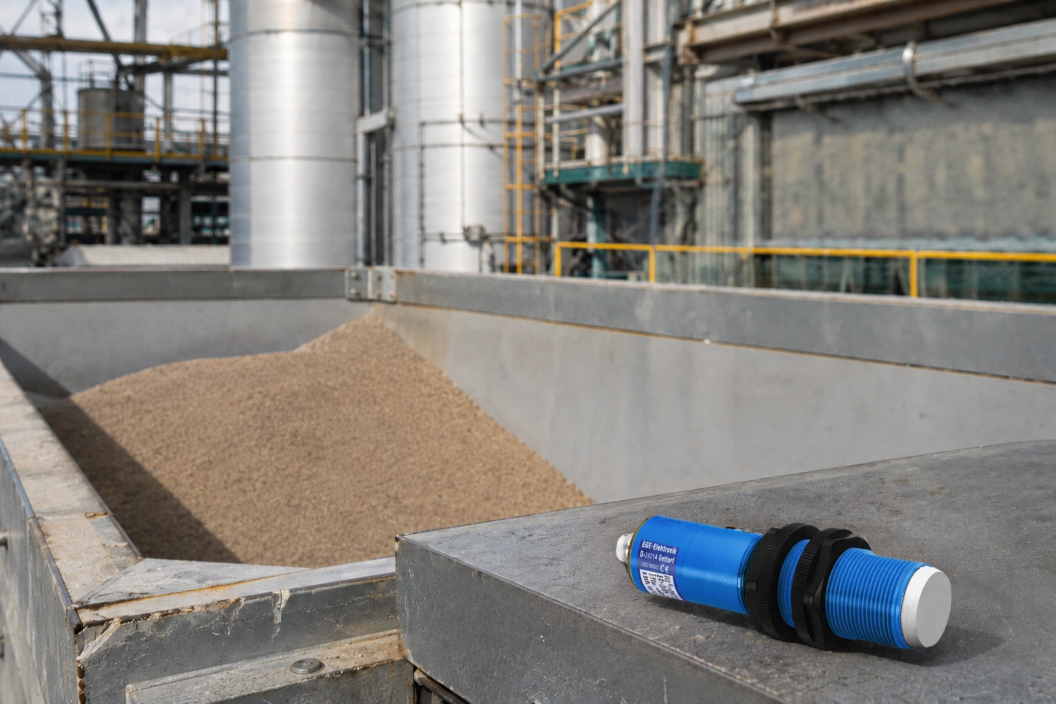
Ultrasonic sensors work by emitting brief pulses of high-frequency sound and measuring the time it takes for the echo to return from the nearest surface. This time-of-flight measurement is converted into a distance reading, which represents the distance from the sensor face to the surface of the material below.
Several characteristics make ultrasonic sensing particularly well-suited for level measurement:
- Non-contact operation — the sensor never touches the material, eliminating wear, contamination, and the maintenance issues associated with float switches or mechanical level gauges
- Insensitivity to target material properties — ultrasonic sensors detect sound reflections, so they work on liquids, powders, granules, and solids regardless of color, transparency, or electrical conductivity
- Continuous analog output — unlike discrete point-level switches that only indicate high or low, an ultrasonic sensor with an analog output provides a continuous measurement of the material level throughout the full range
- Simple installation — the sensor mounts at the top of the vessel pointing downward; no entry into the vessel or contact with the material is required
System Design
Selecting the Right Ultrasonic Sensor
The most critical specification is sensing range. The sensor must be capable of detecting the target from the maximum possible distance — when the bin is empty — all the way down to the minimum distance when the bin is filled to its maximum level. Add appropriate margin to both ends of this range to ensure reliable measurement throughout the full operating cycle.
The sensor must also have an analog output. Common analog output formats are 4-20 mA (current loop) and 0-10 VDC (voltage). The 4-20 mA format is preferred for longer cable runs because current signals are less susceptible to voltage drop and electrical noise than voltage signals. Confirm that the analog output format is compatible with the PLC, controller, or data acquisition system that will receive and interpret the measurement.
Understanding the Blind Zone
Every ultrasonic sensor has a blind zone — a minimum detection distance that begins at the face of the sensor and extends some distance outward. Within the blind zone, the sensor cannot distinguish between the outgoing pulse and the returning echo, making measurement impossible. The blind zone distance varies by sensor model, typically ranging from a few centimeters to several tens of centimeters.
When designing the installation, ensure that the material level will never rise into the blind zone during normal operation. If the bin fills to a level that brings the material surface inside the blind zone, the sensor will be unable to measure — and may generate erratic or invalid readings. Position the sensor high enough in the vessel that the maximum fill level remains below the bottom of the blind zone.
Temperature Compensation
The speed of sound in air is affected by temperature — warmer air carries sound faster, cooler air slower. Because the distance calculation is based on the time of flight and the speed of sound, temperature changes introduce measurement error in sensors without compensation.
Most industrial ultrasonic sensors include automatic temperature compensation, using an integrated temperature sensor to continuously correct the distance calculation. For applications in environments with significant temperature variation — outdoor tanks, unheated storage buildings, or processes with wide temperature swings — confirm that the selected sensor includes temperature compensation and review its specified measurement accuracy across the expected temperature range.
Handling Dust and Vapor
In bins containing dry bulk materials such as grain, wood chips, or powders, the process of filling the bin can create significant dust clouds. Similarly, liquid applications may generate vapor or foam above the surface. Both of these conditions can affect ultrasonic sensor performance by partially absorbing the outgoing pulse or generating false echoes.
For dusty applications, allow time for the dust to settle before relying on a measurement for critical decisions, or select a sensor with a longer pulse duration and greater acoustic power that is better equipped to penetrate moderate dust conditions. For foam or vapor applications, consult the sensor manufacturer's guidance on whether the sensor's acoustic frequency and power level are appropriate for the specific conditions.
Installation

Mounting Location
Mount the sensor at the top center of the bin if possible, pointing directly downward toward the material surface. Center mounting maximizes the likelihood that the beam hits a flat, horizontal surface rather than an angled pile, which can deflect the echo away from the sensor and reduce measurement accuracy.
If center mounting is not possible due to bin geometry or fill system components, mount the sensor off-center but still as close to vertical as practical. Avoid mounting locations where material will pile up directly beneath the sensor, as an uneven surface creates measurement variability as the material level changes.
Ensure the sensor is located away from fill openings or discharge chutes where falling material could strike the sensor face. Protect the sensor from physical impact with a guard if necessary.
Wiring and Interface
Connect the sensor's analog output to the appropriate input on the PLC or controller. For a 4-20 mA output, the PLC's analog input card receives the current signal; for 0-10 VDC, a voltage analog input is required. Document the wiring thoroughly — including wire colors, terminal numbers, and the PLC address — for future maintenance reference.
Calibration and Scaling
With the sensor installed and wired, establish the measurement reference points:
- Empty bin reading — empty the bin as completely as possible and record the analog output value from the sensor. This represents the maximum measurable distance (lowest material level).
- Full bin reading — fill the bin to the desired maximum level and record the analog output value. This represents the minimum measurable distance (highest material level).
These two readings define the span of the measurement. Program the PLC to scale the analog input value linearly between these two reference points to produce a meaningful level reading in the desired engineering units — percentage full, volume in cubic feet, or weight in tons, for example.
Control Actions Based on Level
Once the analog level measurement is available in the PLC or controller, it can be used to automate a wide range of process responses:
- High-level alarm — alert operators or shut down fill systems when the bin reaches a specified maximum level, preventing overflow
- Low-level alarm — warn operators or trigger an automatic refill request when the level drops to a minimum threshold
- Proportional fill control — modulate a fill conveyor or pump speed based on the measured level to maintain a target fill level continuously
- Inventory reporting — log level readings periodically to track consumption rates, calculate remaining capacity, and support purchasing decisions
- Multiple setpoints — establish intermediate levels that trigger different control actions, such as staging the operation of multiple discharge conveyors as the level drops
The combination of a reliable ultrasonic sensor, a correctly configured analog input, and thoughtful PLC programming delivers a level measurement system that requires minimal operator attention while providing the visibility needed to keep material handling processes running efficiently.
Ongoing Maintenance
Ultrasonic sensors used for level measurement require periodic verification to ensure continued accuracy. Recommended maintenance steps include:
- Sensor face inspection — clean the sensor face if material dust or condensation has accumulated, as buildup can dampen the acoustic signal
- Span verification — periodically verify the sensor reading against a physical measurement (dip stick, sight glass, or weight reading) at both high and low levels and recalibrate if drift has occurred
- Temperature calibration check — if significant seasonal temperature changes are observed, verify that measurement accuracy is maintained across the full temperature range
With proper selection, installation, and maintenance, an ultrasonic level measurement system provides years of reliable, low-maintenance service in a wide variety of bulk material storage applications.