| Amplifier will not power ON. |
Check the silver tag on the back of the amplifier to determine the correct supply voltage for that model. Using a volt meter, test across pins 2 and 10 for the correct voltage reading. |
| Amplifier will not power ON. (Part 2) |
If the correct power is present on pins 2 and 10, remove the amplifier from the socket and inspect the sides for discoloration or bulging of the plastic housing. Is the amplifier hot or producing a strong odor? If so, the amplifier may be damaged due to voltage spike (ie: lightning) and should be replaced. |
| Output status light remains illuminated constantly. |
Use the amplifier's built-in diagnostics to determine if there is a connection or alignment problem. (PDF file: Diagnostic instructions for Pantron Automatic Amplifiers) |
| Amplifier diagnostics report "no signal." (via Output Status/No Signal LED) |
The photo eyes cannot see each other. Check for obstructions between the photo eyes. Clean the face of each photo eye with a mild non-abrasive detergent. Align the photo eyes using the "string method" (shown below) of stretching a string or wire between the photo eyes so that the string passes by the eye in parallel. If both photo eyes are parallel to the string, the alignment should be correct. Check for cracks or deep scratches in the face of the photo eye. Water intrusion through a crack could damage the photo eye circuitry. If either photo eye appears damaged replace it immediately. |
| Amplifier diagnostics report "low signal strength." (via Automatic-Function/Signal Strength LED |
The photo eyes are both functioning, but have limited visibility. Clean the face of each photo eye with a mild non-abrasive detergent. Align the photo eyes using the "string method" (shown below) of stretching a string or wire between the photo eyes so that the string passes by the eye in parallel. If both photo eyes are parallel to the string, the alignment should be correct. Check for cracks or deep scratches in the face of the photo eye. Water intrusion through a crack could damage the photo eye circuitry. If either photo eye appears damaged replace it immediately. |
| Amplifier diagnostics report "transmitter short." (via Upper Transmit Channel/Transmitter Fail LED |
The red and black wires of the transmitter that connect to the automatic amplifier are touching. These wires connect to pin 5(red) and pin 7(black). The shorting of the wires may occur anywhere between the photo eye body and the amplifier socket. Check all splices and terminal strips for incorrect connections. If the wires are not protected by conduit in any area, check the outer sheath of the cable to see if it is brittle. If any problem areas are found in the wires, cut and splice them. Solder the connection and protect it from moisture. If lengths of the wire need to be replaced, use at least .22 gauge conductors. If no problem is found in the transmitter wires, the problem may be the amplifier socket. Replace any defective parts. |
| Amplifier diagnostics report "transmitter open." (via Upper Transmit Channel/Transmitter Fail LED |
One or both of the red and black wires of the transmitter that connect to the automatic amplifier are disconnected. These wires connect to pin 5(red) and pin 7(black). The interruption of the wires may occur anywhere between the photo eye body and the amplifier socket. Check all splices and terminal strips for incorrect connections. If the wires are not protected by conduit in any area, check the outer sheath of the cable to see if it is brittle. If any problem areas are found in the wires, cut and splice them. Solder the connection and protect it from moisture. If lengths of the wire need to be replaced, use at least .22 gauge conductors. If no problem is found in the transmitter wires, the problem may be the amplifier socket. Replace any defective parts.
|
| Amplifier diagnostics report "receiver short." (via Lower Transmit Channel/Receiver Fail LED |
The yellow and silver (shield) wires of the receiver that connect to the automatic amplifier are touching. These wires connect to pin 6(yellow) and pin 8(silver). The shorting of the wires may occur anywhere between the photo eye body and the amplifier socket. Check all splices and terminal strips for incorrect connections. If the wires are not protected by conduit in any area, check the outer sheath of the cable to see if it is brittle. If any problem areas are found in the wires, cut and splice them. Solder the connection and protect it from moisture. If lengths of the wire need to be replaced, use at least .22 gauge shielded conductors. If no problem is found in the transmitter wires, the problem may be the amplifier socket. Replace any defective parts. |
| Amplifier diagnostics report "receiver open." (via Lower Transmit Channel/Receiver Fail LED |
One or both of the yellow and silver (shield) wires of the receiver that connect to the automatic amplifier are disconnected. These wires connect to pin 6(yellow) and pin 8(silver). The interruption of the wires may occur anywhere between the photo eye body and the amplifier socket. Check all splices and terminal strips for incorrect connections. If the wires are not protected by conduit in any area, check the outer sheath of the cable to see if it is brittle. If any problem areas are found in the wires, cut and splice them. Solder the connection and protect it from moisture. If lengths of the wire need to be replaced, use at least .22 gauge shielded conductors. If no problem is found in the receiver wires, the problem may be the amplifier socket. Replace any defective parts.
|
| Output Status LED intermittently flickers |
Use the amplifier's built-in diagnostics to determine if there is a connection or alignment problem. (See link at the bottom of this page for diagnostic help. Since the problem is intermittent, the amplifier diagnostics may not be able to diagnose the problem. Clean the face of each photo eye with a mild non-abrasive detergent. Align the photo eyes using the "string method" (shown below) of stretching a string or wire between the photo eyes so that the string passes by the eye in parallel. If both photo eyes are parallel to the string, the alignment should be correct. Check for cracks or deep scratches in the face of the photo eye. Water intrusion through a crack could damage the photo eye circuitry.
|
| Output Status LED intermittently flickers. (Part 2) |
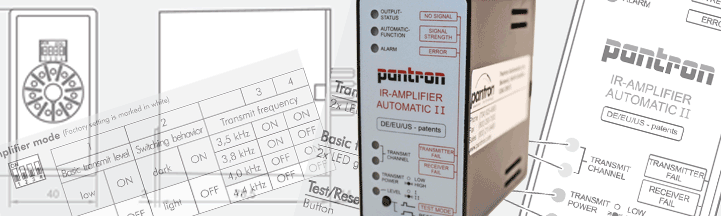
The transmit power adjustment of the amplifier may be set too low for the application. Using DIPswitches 1 and 2, adjust the amplifier to a higher setting. (See diagram printed on the side of the amplifier) Look closely at the receiver photoeye while the problem is occuring. If the receiver is mounted in direct sunlight, this may cause intermittent false signals. Verify that pin 7 on the amplifier socket, also transmitter (black), shares a connection to Earth ground. If either photo eye appears damaged replace it immediately.
|
| Output Status LED will not turn ON. |
The transmit power adjustment of the amplifier may be set too high for the application. Using DIPswitches 1 and 2, adjust the amplifier to a lower setting. (See diagram printed on the side of the amplifier) Verify that pin 7 on the amplifier socket, also transmitter (black), shares a connection to Earth ground. If either photo eye appears damaged replace it immediately |
| Output Status LED will not turn ON. (Part 2) |
If more than one set of photo eyes are in-use in the same area, verify that there is no "crosstalk" between the systems. If two sets of photo eyes are operating on the same frequency, the receiver of one set may see light from the transmitter of another set. To correct this, change the transmit frequency of one set using DIPswitch 4. |
| Amplifier responds the opposite of its expected operation |
If the amplifier outputs when it shouldn't and doesn't output when it should, the problem may be the setting of the "switching behavior." To correct this, adjust DIPswitch 3 to the opposite setting and test the performance of the system. The "switching behavior" or "Light/Dark" setting of the amplifier controls when the amplifier activates the output, either when the receiver sees light from the transmitter (light switching) or when it doesn't (dark switching) |