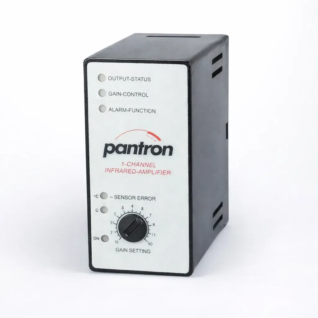
The ISG-N128 combines sensor control with a relay change-over output, NPN transistor switching, and alarm output. It is intended for supervised through-beam systems that need both relay interfacing and transmitter / receiver error indication.
Catalog source: Pantron catalog pages 21-25, depending on model. Values shown here follow the published catalog page for this specific amplifier variant.
| Operating voltage | See order code table |
|---|---|
| Operating basis | Modulated infrared light |
| Transmit frequency | 3.0 / 3.3 / 3.7 / 4.0 kHz |
| Transmit power | Manual |
| Basic transmit level | Low / High |
| Switching behaviour | Light / Dark |
| Switching delay | - |
| Housing material | Plastic |
| Relay output | Change over, 5 A / 230 V AC (24 V DC) |
|---|---|
| Transistor output | NPN, 100 mA / 30 V DC |
| Reaction time | 16 ms (low) / 70 ms (high) |
| Alarm output | AC: NPN / DC: NPN / PNP, 100 mA / 30 V DC |
| Test input | - |
| Connection | 11-pole DIN-plug |
| Protection class | IP40 (EN 60529) |
| Dimensions | 40 x 76.5 x 80 mm |
| Supply | Order code |
|---|---|
| 230 V AC / ±10% / 3.8 VA | ISG-N128/230VAC |
| 115 V AC / ±10% / 3.8 VA | ISG-N128/115VAC |
| 24 V AC / ±10% / 3.8 VA | ISG-N128/24VAC |
| 24 V DC / ±20% / 2.0 W | ISG-N128/24VDC |
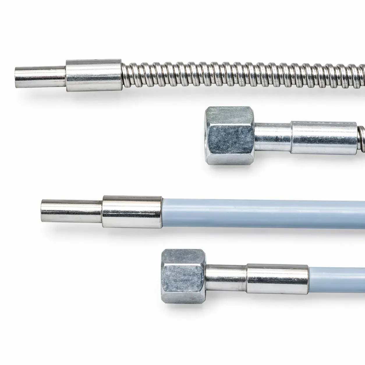
Accessories listed in the catalog for this family include PanBox 1x1 protective enclosure, ISO1 11-pole DIN socket, and RTC 11 retaining clip.
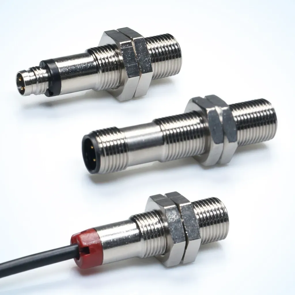
| Transmitter family | Receiver IRL-... | Receiver IR-... |
|---|---|---|
| Transmitter IT-..., ITL-... | 10 m | 20 m |
| Transmitter IT-...HP, ITH-... | 20 m | 35 m |
| Transmitter ITA-... | 35 m | 55 m |
Maximum range depends on the selected Pantron transmitter / receiver pair and installation conditions.


Share a few details below and our team will respond with recommended options, pricing, and lead time.