Pantron Infrared Photoelectric Amplifiers |
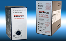
There are two types of Pantron amplifiers, manual, (ex. model ISG-N24), which allows the user to manually adjust the gain setting, and automatic amplifiers, (ex. model ISG-A124.) The amplifier is the controller for the Pantron photo eyes and plugs into an 11-pin socket. The transmitter and receiver photo eyes connect to this socket as well as the power supply for the amplifier and the output connections for the equipment to be controlled.
The amplifier sends a modulated signal to the transmitter photo eye. The transmitter converts this signal into an infrared beam of light, which is projected up to 100 feet. The intensity of the infrared beam may be controlled to compensate for the environmental conditions of different applications. In a car wash, for example, the intensity of the beam should be strong to penetrate the spray, soap, dirt, and fog. In an application where smaller objects are being detected, for instance, on a conveyor, the intensity of the beam should be lower so that the beam does not illuminate the object and pass around the sides. The receiver photo eye detects this infrared beam of light and returns a signal to the amplifier. If the signal returned to the amplifier matches the correct frequency, then the amplifier reports that the photo eyes have visual contact. Incorrect frequencies are ignored, which is helpful in reducing false signals due to extraneous light sources.
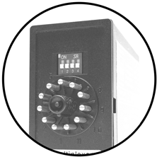
On the back of the amplifiers, in addition to the quick disconnect pins, there is a bank of four Dipswitches. These switches are used to set the features previously described. These settings vary based upon the model of amplifier being used. When setting a Pantron automatic amplifier, the first two Dipswitches are used together to control the level of intensity of the infrared beam. The third Dipswitch controls a feature known as light and dark mode. If dark mode is selected, the amplifier will register an output when the infrared beam is interrupted. If light mode is selected, the output will remain ON until the beam is interrupted. The fourth Dipswitch selects the frequency that the transmitter will use to transmit its beam.
Pantron automatic amplifiers (ISG-Axx) have a special diagnostic function that enables a user to troubleshoot the photo eyes without technical assistance. The button on the face of the amplifier, when held for two seconds causes the amplifier to reset, but when it is only pushed briefly, it causes the amplifier to enter diagnostic mode. In diagnostic mode, the text on the right-hand side of the face of the amplifier is used as a reference to interpret the amplifier’s report, which is delivered through a series of flashing LED’s. Most Pantron manual amplifiers (ISG-Nxx) do not include a diagnostic mode.
Amplifier Selection Guide
Part number |
Number of Channels |
Switching mode |
Number of frequencies |
Built-in diagnostics |
Switching delay |
Test input |
Transistor output |
Relay output |
Alarm output |
Basic transmit levels |
Automatic gain control |
Teach function |
Analog output |
|---|---|---|---|---|---|---|---|---|---|---|---|---|---|
| ISG-A102 | 1 | Both | 2 |  |
|
|
|
4 | |
||||
| ISG-A113 | 1 | Light | 1 | |
|
2 | |
||||||
| ISG-A114 | 1 | Light | 1 | |
|
2 | |
||||||
| ISG-A123 | 1 | Both | 2 | |
|
|
|
4 | |
||||
| ISG-A124 | 1 | Both | 2 | |
|
|
|
4 | |
||||
| ISG-A133 | 1 | Both | 2 | |
|
|
|
|
4 | |
|||
| ISG-A134 | 1 | Both | 2 | |
|
|
|
|
4 | |
|||
| ISG-A143 | 1 | Both | 2 | |
|
|
|
2 | |
|
|||
| ISG-A144 | 1 | Both | 2 | |
|
|
|
2 | |
|
|||
| ISG-N14 | 1 | Light | 1 | |
1 | ||||||||
| ISG-N24 | 1 | Both | 4 | |
|
|
2 | ||||||
| ISG-N27 | 1 | Both | 4 | |
|
|
2 | ||||||
| ISG-N34 | 1 | Both | 4 | |
|
|
|
2 | |||||
| ISG-N37 | 1 | Both | 4 | |
|
|
|
2 | |||||
| ISG-N127 | 1 | Both | 4 | |
|
|
2 | ||||||
| ISG-N128 | 1 | Both | 4 | |
|
|
|
2 | |||||
| ISG-N137 | 1 | Both | 4 | |
|
|
|
2 | |||||
| ISG-N138 | 1 | Both | 4 | |
|
|
|
|
2 | ||||
| ISM-1000 | 1 | Light | 1 | |
|
1 | |||||||
| ISM-1100 | 1 | Both | 4 | |
|
|
2 | ||||||
| ISM-1200 | 1 | Both | 2 | |
|
|
|
2 | |
|
|||
| ISM-1220 | 1 | Both | 2 | |
|
|
|
|
2 | |
|||
| ISM-1510 | 1 | Dark | 1 | |
1 | ||||||||
| ISM-1515 | 1 | Dark | 1 | |
1 | ||||||||
| ISM-1520 | 1 | Both | 1 | |
2 | ||||||||
| ISM-1525 | 1 | Both | 1 | |
2 | ||||||||
| ISM-1530 | 1 | Both | 1 | |
|
2 | |||||||
| ISM-1535 | 1 | Both | 1 | |
|
2 |